


An MPO fiber cable is a fiber optic cable that uses a multi-fiber push-on connector to carry several optical fibers through a single interface. MPO cables are commonly used in backbone links, equipment rooms, enterprise networks, and data centers where many fiber connections need to be routed and managed within limited rack and pathway space.
That density requirement is a major reason MPO has become common in data centers, enterprise backbones, and other fiber-intensive environments. Multi-fiber connectors allow several optical paths to be presented through a single interface, which can reduce the number of individual connections required in high-density cabling systems.
Choosing the right MPO cable still requires careful specification. Fiber count, polarity, connector gender, keying, fiber mode, cable length, and transceiver compatibility all affect whether the link works as intended. This guide explains how MPO fiber cables work, the main configurations available, where they are used, and what to verify before selecting one.
What is an MPO Fiber Cable?
An MPO fiber cable is a fiber optic cable terminated with a Multi-Fiber Push-On connector that brings multiple optical fibers together in a single connector interface. The MPO design uses a multi-fiber ferrule and precision alignment features so several fiber positions can be mated simultaneously. This makes MPO well suited to high-density backbone cabling, pre-terminated fiber systems, and parallel-optics applications that transmit across multiple fibers at the same time.
The connector format is standardized. US Conec identifies IEC 61754-7-1 and IEC 61754-7-2 as commonly cited international standards for MPO connectors, while TIA-604-5, also known as FOCIS 5, defines the Type MPO connector interface in the United States. TIA has also reaffirmed the MPO standard and its alignment with the IEC connector family.
In practice, MPO is commonly used where many fibers need to be carried between racks, telecommunications spaces, or patching locations. A pre-terminated MPO trunk can carry multiple fiber paths through a single cable assembly and then transition through cassettes, adapter panels, or breakout assemblies to equipment-side connections. This can reduce the number of individual duplex assemblies routed through high-density environments, although the complete channel still needs to account for fiber count, polarity, connector gender, keying, fiber mode, and equipment compatibility.
For broader installation guidance, see TTI Cable’s How to Install Fiber Optic Cables for Reliable Network Performance
MPO Meaning and Basic Definition
MPO stands for Multi-Fiber Push-On. The defining feature is the multi-fiber ferrule inside the connector, which holds several optical fibers in a fixed array so they can be connected at the same time.
US Conec explains that fiber alignment in an MT ferrule depends on the position of the fibers and alignment-pin holes, with alignment established by precision pins during mating. Precision matters because every fiber in the array must line up closely with its corresponding fiber on the mating connector. From a network-design perspective, this gives MPO three practical uses:
- carrying multiple fibers through one compact connector.
- supporting pre-terminated backbone and trunk assemblies.
- connecting parallel-optics interfaces that use several fibers for transmit and receive lanes.
An MPO cable should therefore be specified as part of a complete optical channel. Simply knowing that a cable has an MPO connector does not tell you whether it will work with the intended equipment.
How MPO Differs From Duplex Fiber Connections
A conventional duplex fiber link typically uses two fibers, one for transmit and one for receive. LC duplex connectors are common in these applications because they provide a compact two-fiber interface for point-to-point links. MPO changes how those fibers are packaged and managed. A single MPO connector can carry several fibers, allowing one trunk cable to transport multiple duplex channels or support a parallel fiber application.
For example, an enterprise backbone might use an MPO trunk between two telecommunications rooms, then transition those fibers through cassettes into individual LC duplex ports at each end. The equipment still uses conventional duplex connections, but the permanent backbone carries those channels through a smaller number of multi-fiber assemblies.
That makes MPO especially useful when:
-
many duplex channels share the same pathway
-
rack or panel space is limited
-
the project uses factory-terminated backbone assemblies
-
the active equipment uses a parallel fiber interface
For a low-fiber-count point-to-point link, LC duplex may remain simpler to install, inspect, test, and replace. MPO becomes more useful as connection density and fiber count increase.
Read More: Fiber Optic Cable vs Copper Cable: Key Differences
MPO vs. MTP: What Is the Difference?
Note: MPO is the standardized connector format. MTP® is US Conec’s branded implementation of an MPO connector.
US Conec describes MTP® as a high-performance MPO connector that complies with MPO interface standards while incorporating its own mechanical and optical design features. The company also states that standards-compliant MTP connectors can intermate with standards-compliant generic MPO connectors.
The distinction matters when reviewing specifications or purchasing cable assemblies:
In other words, seeing “MPO” or “MTP” on a product description is only the starting point. The cable still has to match the rest of the fiber channel mechanically and optically.
How Does an MPO Connector Work?
An MPO connector aligns multiple optical fibers within a single ferrule so several fiber paths can be connected at once. When two MPO interfaces are mated, guide pins, guide holes, and the connector key control the physical alignment of the ferrules and the orientation of the fiber array.
That makes MPO more sensitive to specification errors than a conventional duplex connection. If the connector gender, keying, polarity, or fiber mapping is wrong, the cable may fit physically but still fail to establish the intended optical path. Contamination can also affect several fibers in the same connection, so inspection and cleaning are especially important in high-density MPO systems.
ANSI/TIA-568.3-E addresses optical fiber array connectivity, polarity methods, and testing requirements. It recommends choosing a polarity method before installation and applying it consistently throughout the channel because different polarity methods are not necessarily interoperable.
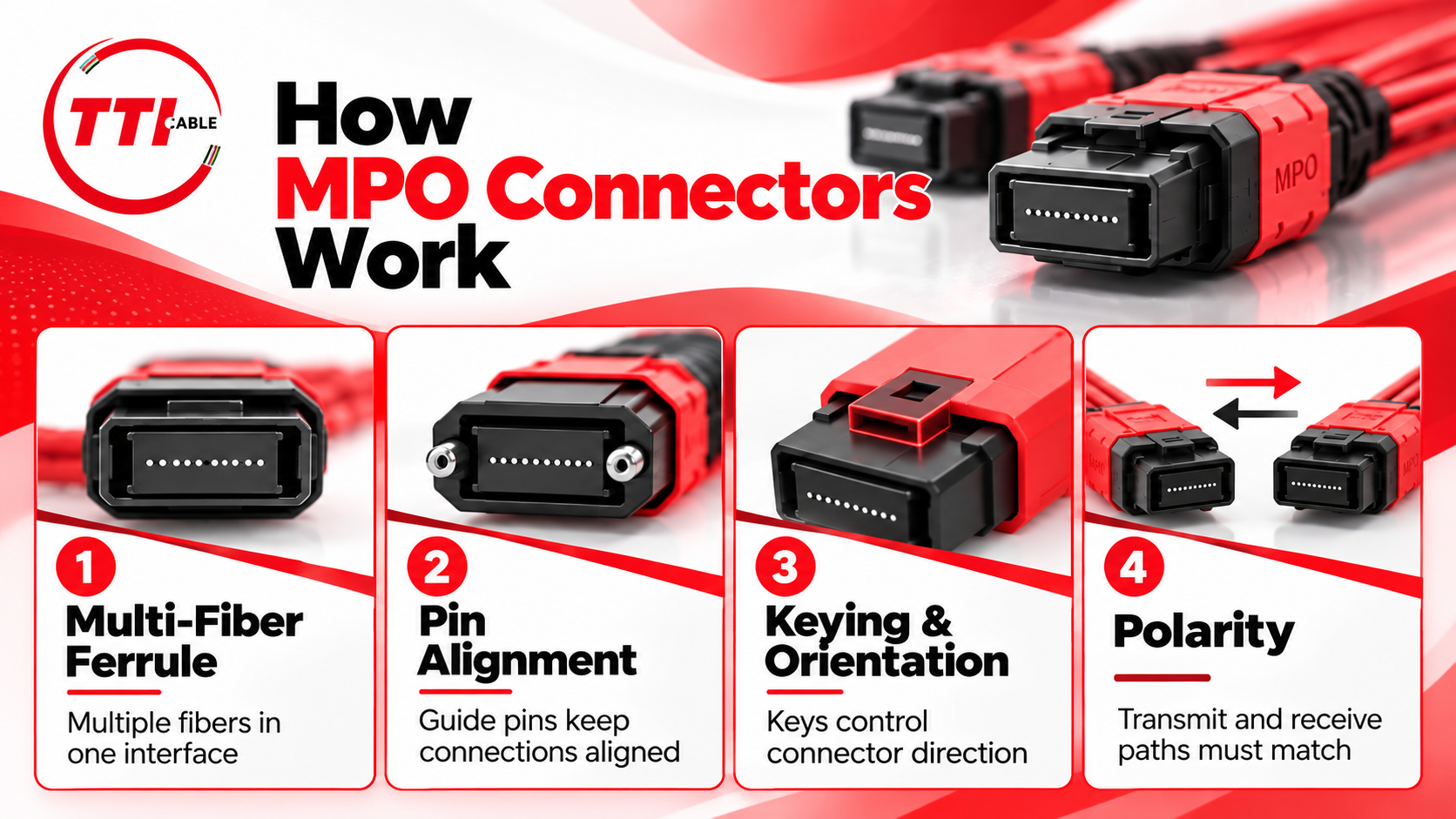
Multiple Fibers in a Single Ferrule
The MPO ferrule holds several fibers in fixed positions so they can be aligned and connected. Common MPO configurations include 8, 12, 16, and 24 fibers, although higher-count designs are also available. The correct fiber count depends on how the link will be used. A trunk carrying several duplex channels may use most or all of its available fibers, while a parallel-optics application may use only specific positions within the connector.
This distinction matters because the number of fibers inside the connector does not always match the number of active optical lanes. For example, a 12-position MPO interface may be used in an application that only requires eight active fibers. In that case, some positions remain unused. Specifying the cable based only on the physical connector count can create unnecessary complexity or compatibility problems later.
The practical rule is simple: match the MPO fiber count to the actual application, transceiver, and channel design.
Guide Pins and Connector Alignment
MPO ferrules use precision guide pins to maintain alignment when two connectors are mated. This creates the familiar male and female MPO terminology:
- Male MPO connectors contain guide pins.
- Female MPO connectors contain guide holes but no pins.
The correct gender depends on what the cable will connect to. A patch cord connected directly to a transceiver may require a different configuration from a trunk cable connecting two cassettes. For that reason, connector gender should be verified at every mating point in the channel.
A typical cassette-based link may look like this:
Cassette → MPO trunk → Cassette
A direct parallel-optics link may instead look like this:
Transceiver → MPO patch cable → MPO trunk or adapter → Transceiver
Both use MPO connectivity, but the required male and female interfaces may differ.
Keying and Orientation
The key on the connector controls how the MPO ferrule is oriented when it is inserted into an adapter or equipment interface. Two common orientations are:
-
Key-up to key-down
-
Key-up to key-up
This affects how fiber positions line up from one end of the cable to the other. For example, the fiber located in position 1 at one end may remain in position 1, move to the opposite side of the array, or be paired differently depending on the polarity method and connector orientation.
This is why a specification such as “12-fiber MPO-to-MPO cable” is incomplete. A usable MPO cable specification should also identify:
- fiber count
- polarity
- connector gender
- key orientation
- fiber mode
- connector polish
- cable length
- end-A and end-B configuration.
These details prevent a common field problem: receiving a cable that looks correct, connects physically, and still does not map the fibers where the network design expects them.
MPO Polarity
MPO polarity describes how fiber positions are mapped through the optical channel so transmit lanes connect to the correct receive lanes. Methods A, B, and C use specific combinations of trunk cables, adapters, and patch cords to maintain polarity across the complete channel. The corresponding trunk cable mappings are commonly described as Type A, Type B, and Type C.
A Type A trunk uses a straight-through arrangement. Type B reverses the fiber sequence, while Type C swaps adjacent fiber pairs. Cable type should not be selected in isolation. The trunk, cassettes, adapters, breakout cables, patch cords, and equipment interfaces must work together to provide the correct end-to-end transmit-to-receive paths.
That is why polarity should be treated as a channel-level design decision, not simply as a cable attribute. Mixing polarity methods can produce a link where every connector mates correctly, but the transmit lanes terminate on the wrong fibers. In practice, this is one of the most important details to confirm before ordering an MPO cable system.
What Fiber Counts Are Available in MPO Assemblies?
MPO assemblies are available in several fiber counts, with 8-, 12-, 16-, and 24-fiber configurations among the most common. The right choice depends on the transceiver interface, number of duplex channels, breakout design, polarity method, and whether the link uses parallel optics.
Fiber count should be selected around the actual application. A higher-count MPO cable can carry more fibers, but that does not mean every position will be used.
8-Fiber MPO
An 8-fiber MPO configuration is commonly used in parallel-optics applications with four transmit and four receive fibers. The cable should match an optical interface designed for eight active fibers rather than being selected simply because the application operates at a high data rate.
12-Fiber MPO
A 12-fiber MPO is commonly used in trunks between patching locations, telecommunications rooms, and cassettes. Depending on the architecture, the fibers may support several duplex channels, or only a portion of the positions may be active. The breakout and polarity scheme should therefore be documented clearly.
16-Fiber and Higher-Density MPO
16-fiber and 24-fiber MPO configurations can reduce the number of separate trunks required between dense patching locations. Because more channels are concentrated into one assembly, labeling, testing, and documentation become increasingly important. The selected fiber count should match the channel design and expected capacity rather than density alone.
Singlemode vs. Multimode MPO Fiber Cables
MPO describes the connector format, not the fiber type. An MPO fiber cable can use either singlemode or multimode fiber, and the correct choice depends on the transceiver, required distance, wavelength, and network architecture. This is one of the most important specification decisions because two MPO cables can look almost identical while being designed for very different optical systems. Connector compatibility alone does not make the fiber compatible.
Multimode MPO
Multimode MPO is commonly used in short-reach, high-density fiber applications, particularly where the active equipment uses parallel optical lanes. Typical multimode MPO systems may use OM3 or OM4 fiber, depending on the required application and reach. In these designs, several fibers may carry separate transmit and receive lanes through a single MPO connector.
A parallel-optics transceiver can use multiple fibers simultaneously, allowing high aggregate bandwidth without relying on a single duplex fiber pair. The main limitation is distance. Multimode reach depends on the Ethernet standard, transceiver, fiber grade, and total channel loss. A cable should therefore be selected based on the actual optical specification rather than a general speed label such as “100G” or “400G.”
Singlemode MPO
Singlemode MPO uses the same multi-fiber connector architecture with singlemode optical fiber. It is typically selected for longer-reach backbone links, campus connections, telecommunications environments, and equipment that uses parallel singlemode optics. Singlemode fiber has a much smaller core than multimode fiber and is designed to carry light over significantly longer distances.
Singlemode MPO systems require careful attention to connector endface geometry, polish, cleanliness, and optical loss. Each connection contributes to the total channel loss, so the specification should account for the complete optical path, including:
-
transceiver type
-
operating wavelength
-
connector polish
-
number of mated connections
-
fiber attenuation
-
insertion loss
-
available optical power budget
How to Choose Between Them
Start with the transceiver specification, not the cable. The active equipment will determine the required fiber mode, wavelength, maximum distance, connector interface, and allowable loss. Once those requirements are known, the MPO cable can be selected to match the application. In practical terms:
-
Use multimode MPO when the optics are designed for short-reach multimode fiber, and the link benefits from high-density or parallel connectivity.
-
Use singlemode MPO when the optics require singlemode fiber, longer reach, or a singlemode parallel interface.
-
Do not mix singlemode and multimode components within the same optical path unless an active conversion device is part of the design.
The safest approach is to treat the transceiver, fiber mode, connector type, polarity, and loss budget as one specification. That prevents a common procurement mistake: ordering an MPO cable that fits the port but cannot support the intended optical link.
Read More: Benefits of Fiber Optic Cable for Large Enterprise Networks
Where Are MPO Fiber Cables Used?
MPO fiber cables are most useful in environments where many optical connections need to share limited rack, panel, or pathway space. They are common in data centers, enterprise backbones, telecommunications rooms, campus networks, and other installations where pre-terminated multi-fiber cabling can reduce the number of individual fiber connections that technicians have to route and manage.
The best fit is usually determined by fiber density, equipment interfaces, and the way the backbone is organized, not by the building type alone. MPO may be used as a direct equipment connection, a trunk between patching locations, or a backbone that transitions to LC duplex ports through cassettes.
High-Density Network Racks
MPO is commonly used in racks where dozens or hundreds of fiber connections need to be concentrated into a small amount of panel space.
A multi-fiber trunk can replace several individual duplex cable runs between patching locations. This reduces the number of cable assemblies passing through rack managers and can make dense backbone connections easier to organize.
The benefit depends on maintaining serviceability. MPO connectors still need enough clearance for inspection and cleaning, and trunk cables need proper bend-radius control and strain relief. A rack that achieves high density but makes connectors difficult to access will be harder to maintain.
Read More: 7 Steps to Choosing the Right Patch Panel for Your Network Rack
Fiber Backbone Connectivity
Backbone cabling is one of the clearest applications for MPO. An MPO trunk can carry multiple fibers between network rooms, floors, racks, or distribution points. At each end, the trunk may connect to an MPO cassette that converts the multi-fiber connection into individual LC duplex ports. A typical arrangement might look like:
MDF cassette or adapter panel → MPO trunk → IDF cassette → LC duplex patch cables → network equipment
This design keeps the permanent backbone separate from shorter equipment-side patching. It can also make moves and changes easier because technicians can reassign duplex ports without replacing the trunk itself.
The backbone should still be planned around the actual number of required fibers, expected growth, pathway capacity, and optical loss. Installing additional fiber positions can provide useful headroom, but excessive unused capacity adds cost and documentation requirements.
Equipment Rooms and IDF/MDF Spaces
MDFs and IDFs often aggregate fiber from multiple floors, buildings, wireless networks, security systems, or network switches. MPO can simplify these connections when the fiber count becomes high enough that individual duplex runs are difficult to manage.
Pre-terminated MPO trunks are particularly useful when cable routes and distances are known before installation. The assemblies can arrive with the required connectors already installed, reducing field termination work. Accurate measurement matters more in this type of deployment. A trunk that is too short may require an additional connection point, while excessive length creates slack that must be stored without violating bend-radius requirements.
Read More: How to Install Fiber Optic Cables for Reliable Network Performance
Data Rooms and Data Centers
Data centers are a major use case for MPO because they combine high port density with large fiber counts and frequent equipment changes. MPO may be used for:
-
backbone trunks between patching areas;
-
switch-to-switch connections;
-
cassette-based fiber distribution;
-
equipment interfaces that use parallel optics; and
-
breakout connections from a higher-speed port to multiple lower-speed ports.
The exact architecture depends on the transceivers. Two 100G or 400G ports may use completely different fiber counts and connector types depending on the optical standard selected. That is why cable speed labels should be treated cautiously. A cable described as suitable for 400G is not automatically compatible with every 400G transceiver. The optical specification determines whether the link requires MPO, LC, singlemode fiber, multimode fiber, or another interface.
Read Next: Active Optical Cables in Data Centers: A Guide to Faster, Smarter Connectivity
Enterprise and Campus Networks
MPO is also useful outside the data center. Enterprise and campus networks may use MPO trunks between buildings, floors, main equipment rooms, and intermediate distribution spaces. The same backbone can support network switches, wireless infrastructure, servers, security systems, and other fiber-connected equipment, depending on the network design.
Campus environments often place more emphasis on distance and long-term capacity than rack density alone. Singlemode fiber may therefore be preferred for longer backbone routes, while multimode MPO can remain practical for shorter equipment-room or building-level links.
The cabling should be planned around the expected service life of the fiber infrastructure. Active equipment may be replaced several times while the backbone remains in place.
Read Next: How to Future-Proof Your Network Cabling Infrastructure
Operations Centers and Other Fiber-Intensive Environments
MPO can also be used in network operations centers, telecommunications facilities, broadcast environments, industrial networks, laboratories, and other installations with concentrated fiber connectivity. The common factor is usually a high number of optical paths between known endpoints.
Before using MPO in these environments, verify that the operational team can support the added requirements for connector inspection, polarity documentation, testing, and replacement inventory. A high-density connector saves physical space, but technicians still need a clear way to identify and troubleshoot each fiber channel.
MPO is most effective when the installation is standardized. Using consistent fiber counts, polarity methods, labeling conventions, and breakout designs across similar locations can make future maintenance much easier.
Why Use MPO Fiber Cabling?
MPO fiber cabling is most useful when a network needs to move a large number of fibers through limited rack, panel, or pathway space. By grouping multiple fibers into a single connector and trunk assembly, MPO can reduce the number of individual cable runs required between distribution points and make high-density fiber systems easier to deploy in a consistent way.
The main benefits come from density, pre-termination, modularity, and repeatability. These advantages are strongest in backbone links, data centers, equipment rooms, and other environments where fiber counts are high enough to justify a multi-fiber architecture.
Higher Fiber Density
A single MPO connector can carry multiple fibers through one interface, reducing the number of separate connections needed between high-density patching locations. This is particularly useful where rack, panel, or pathway space is limited. The tradeoff is concentration. One incorrectly specified, damaged, or disconnected trunk can affect several channels at once, which makes inspection, labeling, and test documentation more important.
Faster Pre-Terminated Deployment
MPO assemblies are commonly factory-terminated, reducing field termination work and helping standardize deployments across racks, rooms, or facilities.
Pre-termination shifts more responsibility into the design phase. Pathway measurements, connector configuration, polarity, and fiber count must be correct before ordering. A trunk that is too short may require an additional connection point, while excessive length creates slack that must be stored and managed.
Cleaner Cable Management
MPO can reduce the number of cable jackets moving through rack managers, overhead pathways, and patching areas. That can make high-density systems easier to organize, particularly when multiple duplex channels travel between the same two points. Fewer trunk assemblies also make it easier to identify major backbone routes at a glance.
Good cable management still requires:
-
adequate bend-radius control
-
accessible connector locations
-
proper strain relief
-
organized slack storage
-
clear labeling at both ends
MPO helps reduce physical clutter, but it does not correct poor routing or documentation practices.
Easier Expansion
A modular MPO backbone can support future growth without replacing the permanent trunk every time additional fiber channels are required. For example, a trunk may be installed with more fiber capacity than the initial deployment uses. Additional channels can later be activated through compatible cassettes, harnesses, or patching components if the original architecture was designed for that expansion.
This approach works best when spare fibers and unused ports are clearly documented. Future technicians need to know which positions are available, how the polarity is mapped, and what equipment the backbone was designed to support.
Standardized, Repeatable Deployments
MPO can also make sense when an organization or integrator needs to deploy the same fiber architecture repeatedly. Across racks, rooms, buildings, or customer sites, a standardized design can define consistent specifications for:
- fiber count
- trunk type
- polarity method
- connector gender
- cassette configuration
- fiber mode
- labeling convention
This can simplify procurement, installation, spare inventory, and troubleshooting. It also reduces the number of one-off cable configurations technicians need to interpret later.
MPO Trunk Cables, Breakout Cables, and Cassettes
MPO systems use several component types depending on how the fibers need to move through the network. The main options are trunk cables, breakout cables, cassettes, and adapter panels. TTI Cable's MTP/MPO Assemblies include multi-fiber connectivity options for applications that require pre-terminated trunk, breakout, or equipment-level connections.
MPO-to-MPO Trunk Assemblies
An MPO trunk cable has MPO connectors on both ends and carries multiple fibers between fixed points such as racks, MDFs, IDFs, or cassettes. Because these assemblies are typically pre-terminated, the specification should be complete before ordering. Fiber count, polarity, connector gender, fiber mode, cable length, and jacket rating all need to match the channel design.
MPO Breakout or Harness Assemblies
An MPO breakout cable uses an MPO connector on one end and multiple individual connectors, often LC, on the other. These assemblies are useful when a multi-fiber interface needs to connect to separate equipment ports. The main concern is fiber mapping. Each fiber position in the MPO connector must terminate at the correct breakout connector.
MPO Cassettes
An MPO cassette distributes the individual fibers from a multi-fiber MPO trunk to separate connector ports, commonly LC duplex, without converting the optical signal. A typical arrangement is:
MPO trunk → Cassette → LC Duplex Patch Cables
Cassettes are useful when the backbone needs high-density MPO connectivity, but the equipment side uses conventional duplex ports. Their insertion loss should still be included in the total optical loss budget. When the design requires an MPO backbone to transition into equipment-side duplex connections, Fiber Patch Panels & Cassettes can provide the termination and distribution point for that transition.
MPO Adapter Panels
An MPO adapter panel provides a pass-through connection between compatible MPO connectors without converting them to LC or another connector type.
These panels are useful when the channel should remain MPO from one segment to the next. The main considerations are connector orientation, polarity, gender compatibility, and clear labeling. For designs that require pass-through fiber connectivity between cable segments or patching locations, TTI Cable also offers Fiber Adapters & Adapter Panels for organizing compatible fiber connections.
What to Consider When Choosing an MPO Fiber Cable
Choosing an MPO fiber cable starts with the active equipment and the optical path it needs to support. The cable should be specified around the transceiver, fiber mode, lane count, distance, and loss budget rather than around a general speed label such as 100G or 400G.
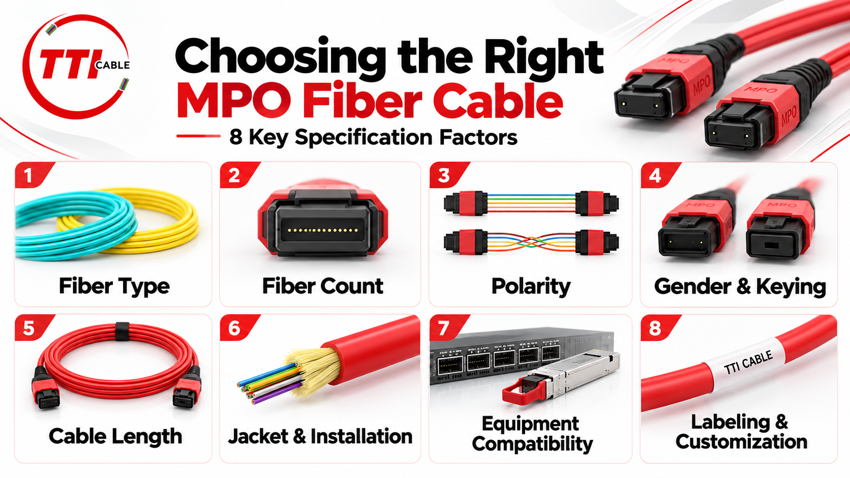
Fiber Type
Confirm whether the link requires singlemode or multimode fiber before selecting the assembly. The transceiver specification should determine the required fiber mode, wavelength, and supported distance. OM3, OM4, and singlemode fiber are not interchangeable simply because they can all use MPO connectors. The connector may fit while the optical link still fails to meet the required reach or performance.
Fiber Count
The fiber count should match the actual number of lanes or duplex channels in the design. An 8-fiber application may not benefit from a 12- or 24-fiber assembly unless the additional capacity is intentional. Extra fibers can be useful for growth, but they should be documented and supported by the broader cabling plan.
Polarity
Polarity determines how transmit fibers at one end of the link reach receive fibers at the other. The MPO trunk, cassettes, breakout assemblies, patch cables, and equipment interfaces all need to follow the same polarity design. If one component uses a different mapping method, the link may connect physically but fail to pass traffic correctly.
Connector Gender and Keying
Connector gender and key orientation affect both mechanical compatibility and fiber alignment. Each end of the cable should be checked against the component it will mate with, whether that is a transceiver, cassette, adapter, or another cable assembly. This is especially important in MPO systems because two connectors can appear similar while using different pinning or orientation.
Cable Length
Pre-terminated MPO cables should be measured against the actual installed pathway. A cable that is too short may require an additional connection point, which adds insertion loss and another location that must be inspected and maintained. Excessive length creates unnecessary slack and can make cable management more difficult.
Jacket and Installation Requirements
The cable construction should match the environment where it will be installed. That may include plenum, riser, indoor, outdoor, or armored requirements, along with pathway dimensions, bend-radius limits, and physical protection. These decisions should be made before the cable is ordered, particularly for custom pre-terminated assemblies.
Equipment and Transceiver Compatibility
The transceiver should ultimately determine whether the selected MPO cable is suitable.
Verify the optical interface, wavelength, fiber mode, lane count, supported distance, and allowable channel loss. Two transceivers operating at the same Ethernet speed can require very different cabling architectures.
When the active optics are also being specified, TTI Cable's Transceivers provide another point of reference for matching the optical interface to the required fiber mode, connector, reach, and network speed.
Labeling and Customization
Clear labeling becomes more important as more fibers are concentrated into one assembly.
The documentation should identify the cable endpoints, fiber count, polarity, fiber mode, connector configuration, and any breakout or cassette mapping. That information helps technicians trace individual channels and makes future replacement or expansion less prone to error. The safest specification is one that allows every fiber path to be traced from the transmitting equipment to the intended receiver before the cable is installed.
Read Next: Custom Cabling Checklist: 10 Questions to Answer Before Manufacturing Begins
MPO Fiber Cable vs. Traditional Duplex Fiber: When Does MPO Make Sense?
MPO and duplex fiber solve different cabling problems. MPO is most useful when a network needs to move many fibers through limited space, support parallel-optics interfaces, or simplify high-count backbone cabling. Duplex fiber is usually easier to work with when the link only needs one transmit and one receive fiber.
The decision should come down to density, equipment compatibility, and how the fiber plant will be maintained over time.
For a backbone carrying many channels between racks or telecommunications spaces, MPO can reduce the number of separate cable assemblies and make better use of panel and pathway space.
For a small point-to-point connection, LC duplex fiber is often the more practical choice. It requires fewer design decisions and is easier for technicians to inspect, test, and replace. The important point is to match the architecture to the requirement. MPO should be used when its density and modularity solve a real cabling problem, not simply because it supports more fibers per connector.
Common MPO Fiber Cable Mistakes to Avoid
Most MPO problems come from specification errors rather than the connector itself. Because one assembly can carry several optical paths, a single mismatch can affect multiple channels. Common mistakes include:
-
Wrong polarity: The cable can mate correctly while transmit and receive lanes map to the wrong fiber positions.
-
Incompatible connector configuration: Gender, keying, fiber count, polish, and internal mapping all need to match the rest of the channel.
-
Wrong fiber type: Singlemode, OM3, and OM4 should be selected according to the transceiver, wavelength, and required reach.
-
Ignoring total insertion loss: Account for fiber attenuation and the insertion loss of all mated connector pairs, splices, cassettes, and other optical components.
-
Poor length planning: Pre-terminated MPO trunks need accurate pathway measurements to avoid added connection points or excessive slack.
-
Weak labeling: A single MPO trunk may represent several channels, so polarity, endpoints, fiber count, and breakout mapping should be documented clearly.
The safest approach is to verify the complete channel before ordering, including the active equipment, trunk, cassettes, patching components, and fiber mapping.
How MPO Supports Scalable Fiber Infrastructure
MPO can support network growth by separating the permanent fiber backbone from the equipment connections that may change over time.
A properly planned MPO trunk can remain in place while cassettes, breakout assemblies, patch cables, or active equipment are updated around it. That can be useful in data centers, enterprise networks, and campus environments where switch and transceiver platforms may change more frequently than the installed fiber plant.
Scalability depends on the original design. The backbone should provide enough fiber capacity for expected growth, use a consistent polarity method, and leave enough optical-loss margin for future patching changes. Spare fibers should also be documented so they can be activated later without tracing the entire trunk again.
This is where MPO can offer long-term value. A standardized trunk architecture can support additional channels or new equipment without requiring the permanent cabling to be replaced each time the network changes.
Choosing the Right MPO Cable Starts With the Complete Fiber Channel
MPO fiber cabling works best when the cable, connector, transceiver, polarity method, and installation environment are specified as one system.
Before selecting an assembly, confirm the fiber mode, number of active fibers, polarity method, connector configuration, and allowable optical loss. Then verify cable length, pathway requirements, jacket rating, and documentation requirements.
MPO is a strong fit for high-density backbones and parallel-optics applications, while duplex fiber may remain the simpler choice for lower-density point-to-point links. The right architecture is the one that meets the actual network requirement without adding unnecessary complexity.
TTI Cable offers MTP®/MPO Assemblies for high-density fiber connectivity, including backbone, breakout, and equipment-level applications. When evaluating an MPO fiber cable, start with the transceiver and channel design, then build the cable specification around those requirements.
Frequently Asked Questions
What MPO cable type should I use for a fiber optic application?
The right MPO cable type depends on the transceiver, fiber mode, number of active fibers, polarity, and required distance. Start with the equipment specification, then choose the matching singlemode or multimode fiber optic cable and connector configuration. A standard MPO connector format alone does not confirm that two assemblies will work together.
How do MPO and MTP connectors differ?
MPO and MTP connectors use the same standardized multi-fiber interface, but MTP® is US Conec’s branded version of the MPO connector. When specifying an MTP connector or another MPO product, still verify fiber count, gender, key orientation, polarity, fiber mode, and optical requirements rather than relying on the connector name alone.
What number of fibers should an MPO fiber optic cable have?
The number of fibers should match the intended optical lanes or duplex channels. Common options include 8-, 12-, 16-, and 24-fiber configurations. For example, some parallel fiber links use eight active fibers, while trunk cables with 12-fiber or 24-fiber MPO connectors may distribute several duplex channels through cassettes or breakout assemblies.
What is the difference between an MPO breakout cable and a fan-out cable?
The terms are often used for the same basic cable type. An MPO breakout cable or fan-out cable has an MPO connector on one end and several lower-count fiber connectors on the other end. For example, an MPO-12 assembly can distribute eight of its fibers to four LC duplex connections, provided the fiber mapping matches the intended application and equipment interfaces.
Can MPO fiber optic cables be used with LC fiber connectors?
Yes. MPO fiber optic cabling is frequently used with LC through cassettes or breakout assemblies. A backbone may use pre-terminated MPO trunk cabling and then transition to duplex fiber connectors at patch panels for equipment connections. This approach combines high-density fiber optic backbone connectivity with the familiarity of LC fiber patch connections at the equipment side.