

1 min read
Don’t Let Bad Cabling Break Your Network: A Complete Guide to Structured Installation
Behind every reliable network is a structured cabling system that quietly does the heavy lifting. While wireless access and cloud platforms get most...
15 min read
Bob joined Turn-key Technologies in 2011, and helped launch TTI Cable, which is the structured cabling division of TTI. Additionally, he created TTI Fiber which is our overseas affiliate for fiber optic cable manufacturing. With over 20 years of experience in both domestic and international trade and sales, Bob has dedicated himself to providing each and every client with the best solution for their networking needs. It has been under Bob’s supervision that he has created an equally experienced ...
Bob Gissubel
Updated on August 14, 2026
Choosing the right patch panel starts with matching it to your structured cabling system. Cable category, shielding requirements, port density, termination method, rack space, and connector compatibility should all be confirmed before selecting a panel. A mismatch can limit channel performance, crowd the rack, complicate cable management, or create unnecessary work during troubleshooting and expansion.
The scale of Ethernet deployment makes these physical-layer decisions significant. According to the Ethernet Alliance’s 2025 Ethernet Roadmap, enterprise and campus networks account for more than one billion Ethernet ports shipped annually, with the majority using BASE-T connectivity at the access layer. Those connections depend on correctly specified cabling and connecting hardware throughout the channel.
For network designers and installers, patch panel selection should account for the horizontal cable, RJ45 or keystone connectivity, patch cords, rack configuration, shielding strategy, and expected port growth. The seven steps below explain how to evaluate these factors and choose a patch panel that fits both the technical requirements of the network and the practical demands of installation and maintenance.
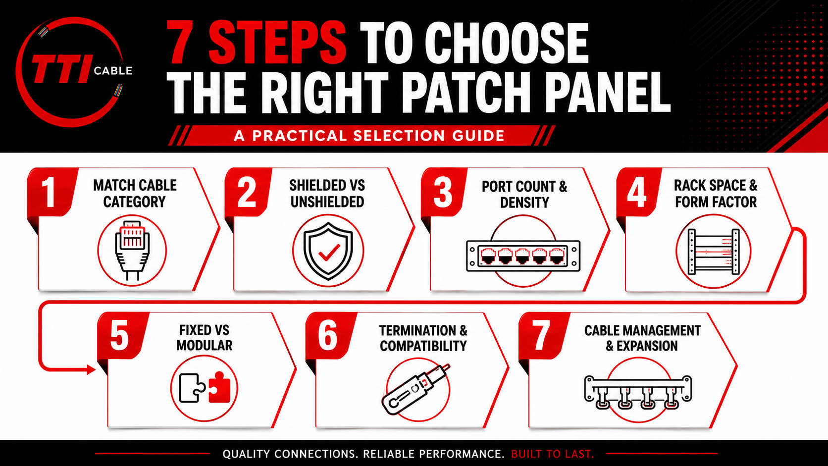
Match the panel to the cable category. Cat5e, Cat6, and Cat6A systems should use compatible connecting hardware throughout the channel.
Confirm shielded or unshielded requirements. A shielded patch panel should be part of a complete shielding, bonding, and grounding design.
Choose port density carefully. A 24-port panel may be easier to service, while a 48-port panel can conserve rack space in denser installations.
Check the termination method. Decide whether a fixed punch-down panel or a modular keystone patch panel better fits the installation and maintenance workflow.
Verify connector compatibility. RJ45 and keystone components may fit physically without supporting the same category, shielding, or conductor specifications.
Plan cable management before installation. Leave enough space for patch cord routing, labeling, rear cable dressing, and technician access.
Allow for realistic expansion. Spare panel ports only help if the rack also has enough switch capacity, cable management, pathway space, and room for additional network cables.
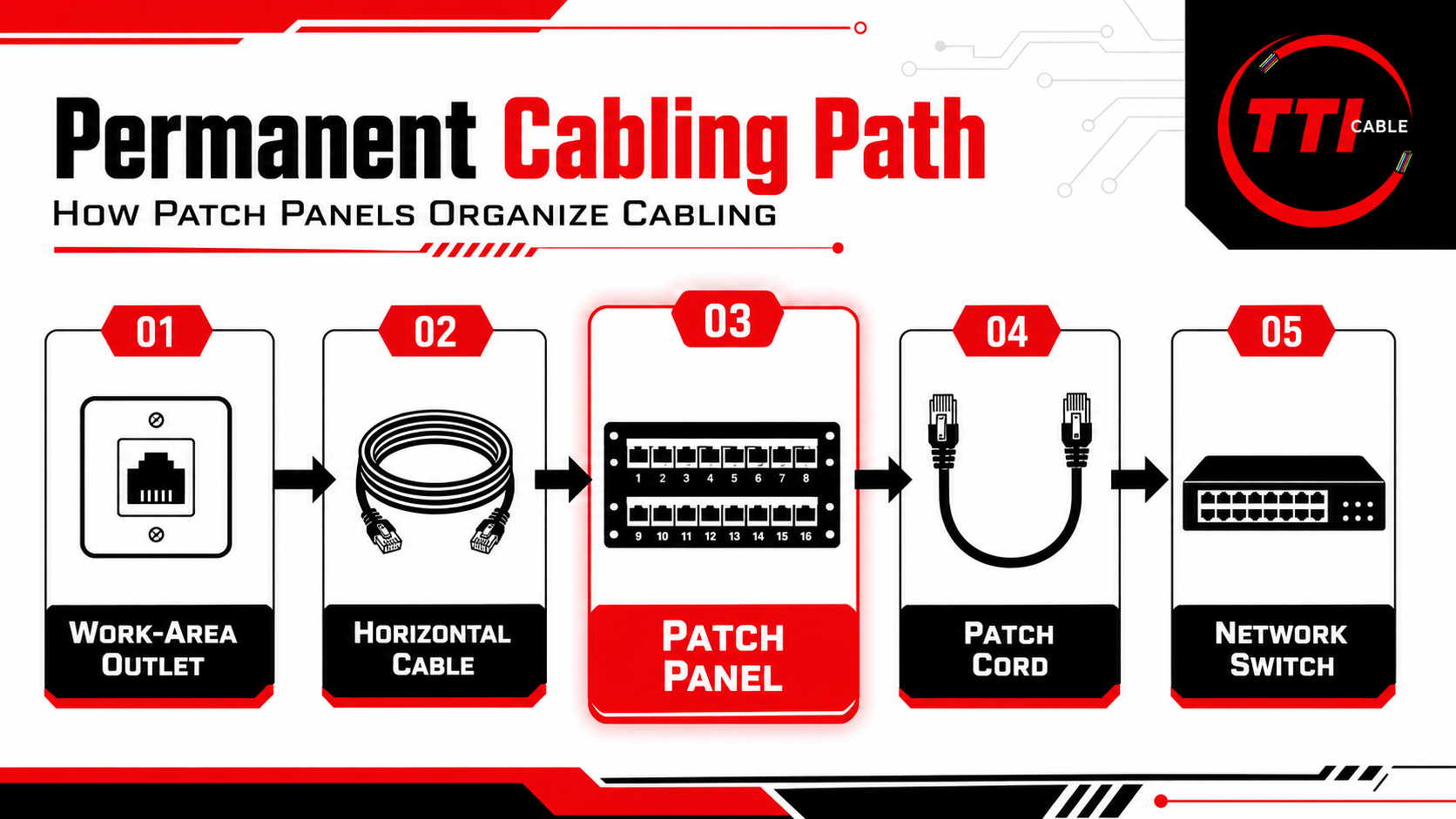
A patch panel provides an organized termination point for permanent network cabling. In a typical copper structured cabling system, horizontal cable terminates at the rear of the panel, while short patch cords connect the front ports to a network switch.
This setup allows us to make network changes at the rack without repeatedly disturbing the permanent cabling. TIA’s current ANSI/TIA-568.2-E, Balanced Twisted-Pair Telecommunications Cabling and Components Standard, covers balanced twisted-pair cabling and connecting hardware used in structured cabling systems.
A typical copper connection follows this path:
Work-Area Outlet → Horizontal Cable → Patch Panel → Patch Cord → Network Switch

The horizontal cable remains fixed, while Copper Patch Cords provide the changeable connection between the patch panel and active equipment. For example, if a Cat6 run serving a workstation needs to move to a different switch port, the technician changes the patch cord at the rack rather than reterminating the horizontal cable. As port counts increase, labeled patch panels also make it easier to trace connections, perform moves and changes, and isolate cabling during troubleshooting.
Patch panels and network switches may both present rows of RJ45 ports, but they serve different functions.
| Rack Component | Primary Role | Function |
|---|---|---|
| Patch Panel | Passive Termination | Organizes and terminates permanent network cabling |
| Network Switch | Active Networking | Forwards Ethernet traffic between connected devices |
| Cable Manager | Cable Routing | Organizes patch cords and controls congestion |
| Fiber Optic Patch Panel | Fiber Termination | Organizes optical fiber connections and patch cords |
| Rack or Cabinet | Physical Support | Holds networking and cabling equipment |
Keeping permanent cabling terminated at the patch panel separates the fixed cabling infrastructure from active network equipment. That gives us a cleaner rack layout and lets technicians change switch assignments without reworking horizontal cable.
The panel we choose affects how easy the rack will be to install, maintain, and expand. Port density influences access to connectors and labels. Panel style affects how terminations are installed or replaced. Available rack space and cable management determine whether patch cords can be routed cleanly.
We therefore treat the patch panel as part of the complete cabling system rather than an isolated rack component. With that foundation established, the next step is to work through the seven decisions that determine which patch panel is the right fit for a given installation.
Read More: Don’t Let Bad Cabling Break Your Network: A Complete Guide to Structured Installation
We recommend choosing a patch panel in a defined sequence rather than starting with port count or rack size alone. The cable category establishes the performance requirement, while shielding, density, form factor, termination method, connector compatibility, and future expansion determine how well the panel will work in the finished rack.
The following seven steps provide a practical way to evaluate those requirements before specifying a panel.

Start by matching the patch panel to the category of the installed copper cabling. If the network is designed for Cat6 performance, the panel, jacks, and patch cords should support the same required category. The same principle applies to Cat5e and Cat6A systems.
We do not treat physical fit as proof of performance compatibility. An RJ45 connector may plug into a port, or a keystone jack may fit a modular panel, while the components still differ in category rating, conductor compatibility, shielding, or termination requirements.
For Cat6A installations, we also pay closer attention to cable diameter, conductor size, rear clearance, and bend management. These details matter more in high-density racks, where larger cable bundles can make termination and cable routing more difficult. Before approving a patch panel, we verify five things:
Category Rating
Cable Type
Conductor Compatibility
Termination Method
Shielding Requirement
This gives us a clear performance baseline before moving on to the next decision: whether the installation should use shielded or unshielded connectivity.
Once the cable category is established, determine whether the installation requires shielded or unshielded connectivity. We base that decision on the cable type and the amount of EMI/RFI exposure in the environment.
| Consideration | Unshielded Patch Panel | Shielded Patch Panel |
|---|---|---|
| Typical Cable Type | UTP copper cabling | Shielded or screened copper cabling |
| Common Environment | Offices, schools, standard telecom rooms | Industrial spaces, equipment rooms, electrically noisy areas |
| EMI/RFI Protection | Relies on a balanced twisted-pair design and proper routing | Adds shielding as part of a complete shielded system |
| Connector Requirements | Compatible with unshielded RJ45 or keystone connectivity | Compatible shielded connectors and patch cords |
| Bonding and Grounding | No shield-continuity requirement | Requires a defined bonding and grounding approach |
| Installation Complexity | Generally simpler | Requires closer attention to shield continuity and bonding |
For a typical Cat6 UTP installation in an office or telecommunications room, an unshielded patch panel is usually the practical choice. Shielded patch panels become more appropriate when cabling runs near motors, variable-frequency drives, heavy electrical equipment, or other persistent sources of electromagnetic interference.
If shielding is required, the patch panel must be compatible with the shielded cable, connectors, and patch cords used in the installation. The rack or cabinet and telecommunications bonding infrastructure also need to support the grounding requirements of the system.
A shielded panel by itself does not provide effective EMI/RFI protection. Shield continuity and proper bonding need to be maintained throughout the installed cabling. ANSI/TIA-607-E, Generic Telecommunications Bonding and Grounding (Earthing) for Customer Premises, provides the relevant framework for telecommunications bonding and grounding infrastructure.
We also avoid using shielding as a substitute for proper cable routing. Separation from electrical infrastructure, correct termination, and appropriate pathways still matter in a shielded installation.
Read Next: Fiber Optic Cable vs Copper Cable: Which One Will Power the Future of Your Network?
Next, decide how many ports the rack needs to support and how much density makes sense for the available space. Port count affects rack capacity, cable management, technician access, and future expansion.
A 24-port panel is often easier to service because there is more room around connectors, labels, and patch cords. A 48-port panel can reduce rack-unit consumption, which may be useful in denser server rooms, data centers, or enterprise telecommunications spaces. Higher density, however, puts more connections into the same working area.
We recommend evaluating the patch panel alongside the switch layout. A 48-port panel paired with a 48-port switch can create an efficient arrangement, but only if the rack has enough horizontal and vertical cable management to keep patch cords organized and ports accessible.
Future growth should also influence the decision. If a 24-port panel will support 20 connections at installation, the remaining four ports may be sufficient for a stable office. They may not be enough if additional wireless access points, cameras, workstations, or building systems are already planned.
The right port density gives us enough capacity without making routine work difficult. Once a panel is fully populated, technicians should still be able to read labels, reach individual RJ45 connectors, and trace patch cords without disturbing neighboring connections.
Once the port count is established, we look at how the panel will fit into the rack as a whole. A patch panel may physically mount in a standard 19-inch rack and still create problems if there is not enough space for switches, cable managers, fiber equipment, power distribution, or future hardware.
Rack-unit consumption matters most in dense environments. A 1U panel can help conserve space, but that advantage disappears if rear cable dressing becomes cramped or technicians cannot comfortably reach the front ports. We also consider how patch cords will leave the panel and whether the surrounding horizontal and vertical managers have enough capacity to support the layout.
Rear clearance deserves the same attention. Larger cable bundles, especially in higher-category installations, need enough room to enter and terminate without tight bends or excessive strain. In crowded racks, poor rear access can make installation and later maintenance unnecessarily difficult.
Before we approve a panel, we review the rack elevation, available rack units, front and rear cable access, and the equipment planned above and below it. The right form factor should fit the rack without forcing compromises in cable routing, serviceability, or future expansion.
Read More: Maximizing High-Speed Data Transmission and Data Center Connectivity with Active Optical Cable (AOC)
The next decision is whether the installation is better suited to a fixed patch panel or a modular keystone panel. Both can support organized copper cabling, but they differ in termination workflow, flexibility, and how easily individual ports can be changed later.
| Consideration | Fixed Patch Panel | Modular Keystone Patch Panel |
|---|---|---|
| Port Design | Ports are built into the panel | Individual keystone jacks install into panel openings |
| Termination | Commonly uses rear punch-down connections | Each keystone jack is terminated separately |
| Best Fit | Standardized installations with consistent cable types | Phased builds or networks that change frequently |
| Port Replacement | Depends on the panel design | Individual jacks can typically be replaced |
| Configuration Flexibility | Lower | Higher |
| Installation Workflow | Efficient for repetitive terminations | Allows ports to be populated as needed |
| Main Planning Concern | Less flexibility if individual ports need changes | Jack compatibility and rear clearance must be verified |
We generally prefer fixed punch-down panels when the cable category is standardized, most ports will be populated from the start, and technicians need a consistent termination layout.
Modular keystone panels make more sense when ports will be added gradually, individual jacks may need replacement, or the rack is expected to undergo frequent moves, adds, and changes. When a modular design is appropriate, TTI Cable's Keystone Jacks provide a relevant reference point when checking jack category, termination, and panel compatibility.
With modular panels, physical fit should not be the only compatibility check. A keystone jack may snap into the panel while differing in category rating, shielding, termination orientation, or supported cable construction. We also check jack depth and cable exit direction because both can affect rear clearance in a densely populated rack.
The choice comes down to how the rack will be used. Fixed panels suit predictable, repeatable installations. Modular keystone panels provide more flexibility when port-level changes are likely over the life of the cabling system.
Before installation begins, confirm that the patch panel supports the exact cable construction and termination method being used. This check helps prevent problems that may not become obvious until the rack is already populated.
For fixed punch-down panels, verify the supported conductor type and wire gauge, along with the required T568A or T568B wiring configuration. For modular panels, check the keystone jack’s category rating, shielding, physical fit, depth, and cable exit direction.
Connector compatibility also deserves a closer look. An RJ45 plug may fit into a port, and a keystone jack may snap into a panel, while the components still differ in performance rating or installation requirements. Mechanical fit should never be treated as proof of full compatibility.
Termination quality matters as well. Excessive pair untwisting, poorly seated conductors, or tight bends immediately behind the panel can create avoidable performance and maintenance issues.
We recommend reviewing the manufacturer’s specifications before termination starts. Confirming conductor size, cable type, shielding, and termination requirements at this stage is far easier than correcting a mismatch after dozens of ports have already been installed.
The final step is to look beyond the patch panel itself and consider how the rack will be managed after installation. A panel can be technically compatible and still create problems if patch cords are difficult to route, labels are obscured, or there is no room for future connections.
We plan front and rear cable management at the same time as the panel layout. Horizontal managers should have enough capacity for the patch cords leaving the panel, while rear cable bundles need adequate support and clearance so they are not bent tightly or placed under unnecessary strain.
Serviceability matters just as much. Technicians should be able to identify a port, remove a patch cord, inspect a connector, and trace a connection without disturbing neighboring cables. Before finalizing the layout, we check:
Whether labels remain visible when the panel is fully populated
Whether patch cords can be routed without crossing or blocking equipment
Whether technicians can reach individual ports during troubleshooting
Whether spare ports are available for expected growth
Whether switches, pathways, and cable managers can support that same expansion
We also avoid planning spare patch-panel capacity in isolation. Ten open ports provide little value if the rack has no available switch ports, pathway space, or cable-management capacity to support the next ten connections.
A well-planned patch panel should make future moves, adds, and changes easier, not force technicians to reorganize the rack every time the network grows.
Read Next: Tips for Choosing Data Center Power Cords: Avoid Downtime with the Right Cable
Once the seven steps are complete, we can reduce the decision to a few practical questions. The goal is to match the patch panel to the cabling system, rack layout, installation environment, and expected operating needs rather than selecting by port count alone.
| Requirement | What to Evaluate | Recommended Direction |
|---|---|---|
| Cable Category | Cat5e, Cat6, or Cat6A performance requirement | Use a patch panel and connecting hardware rated for the required cabling category |
| Electrical Environment | EMI/RFI exposure near motors, drives, or heavy electrical equipment | Consider a properly designed shielded system when interference is a documented concern |
| Port Requirement | Current connections and realistic near-term growth | Select enough capacity without creating unnecessary rack congestion |
| Rack Space | Available rack units, switch placement, front and rear clearance | Choose a density and form factor that leave room for cable management and servicing |
| Panel Style | Frequency of changes, replacement needs, and installation workflow | Use fixed panels for repeatable installations or modular keystone panels where port-level flexibility matters |
| Termination | Conductor size, cable construction, punch-down or keystone method | Verify manufacturer compatibility before installation |
| Maintenance | Label visibility, connector access, patch cord routing | Avoid layouts that make routine troubleshooting difficult |
| Expansion | Future switch ports, pathways, rack capacity, and cable-management space | Plan growth across the entire rack, not only the patch panel |
We use this framework as a final check before specifying a panel. If one of these requirements is still unclear, the patch panel selection is probably premature.
For example, a 48-port Cat6 panel may appear suitable based on port count and category alone. If the rack lacks enough cable-management capacity or technicians cannot comfortably reach the ports once populated, a different density or layout may be the better choice.
The best patch panel is the one that meets the required channel performance while remaining practical to install, maintain, and expand over the life of the network.
Most patch panel problems come from overlooking how the panel fits into the rest of the cabling system. Before finalizing a selection, we watch for a few recurring mistakes:
Mixing cabling categories. A higher-category cable does not preserve its intended channel performance if lower-rated patch panels, jacks, or patch cords are used elsewhere in the link.
Using shielded hardware without a grounding plan. Shielding should be specified as part of a complete shielded and bonded system, not added at the panel alone.
Choosing density over access. A crowded patch field can make labels difficult to read and individual ports harder to reach during troubleshooting.
Leaving no practical growth capacity. Spare panel ports should be planned alongside switch ports, rack space, pathways, and cable management.
Ignoring physical compatibility. Keystone jacks and RJ45 components may fit mechanically while differing in category rating, shielding, conductor support, or installation requirements.
A quick compatibility and rack-layout review before ordering can prevent most of these issues from reaching the installation stage.
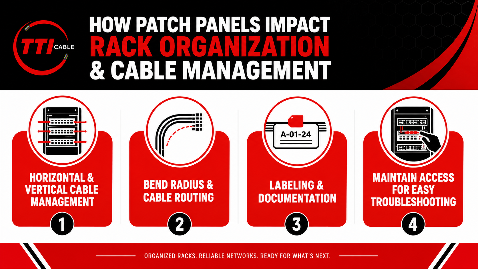
Patch panels influence how cables enter, move through, and leave the rack. Once port count and panel style are set, the surrounding cable-management layout should support that density without blocking access, creating excess slack, or making routine changes harder. A good rack layout should stay manageable after the panel is fully populated, not only when the installation is new.

Horizontal managers guide patch cords across the front of the rack, while vertical managers route larger bundles along the sides. We size both around the expected port density rather than adding them after the rack is populated.
A 48-port panel, for example, places more demand on nearby cable managers than a lightly populated 24-port panel. If those pathways are undersized, patch cords can begin to cross equipment, cover labels, or create unnecessary loops. Switch placement matters as well. Carefully aligning patch panels, switches, and cable managers can reduce patch cord lengths and make individual connections easier to trace.
Patch cords and horizontal cables should be routed without sharp bends, excessive tension, or compression. Rear cable dressing is especially important on high-density panels, where many cables may converge within a small area. We leave enough clearance for cables to transition naturally into trays or managers rather than forcing them around rack hardware. This helps protect the cable and makes later moves or replacements easier to complete.
Port labels should remain readable after the panel is fully populated. Clear labeling allows technicians to identify destinations quickly without tracing cables through an entire bundle.
We also recommend keeping rack documentation aligned with the physical installation. Port assignments, cable IDs, and destination information should be updated whenever connections change. Accurate records become especially useful during troubleshooting, when technicians need to isolate a specific link without disrupting unrelated connections.
Technicians should be able to reach a single port, remove its patch cord, inspect the connector, and trace the connection without disturbing neighboring circuits.
If every small change requires moving several patch cords first, the rack is too congested for efficient maintenance. That is why we treat cable management as part of patch panel planning rather than a finishing detail. The rack should remain practical to service as the network grows and changes.
There is no single patch panel that fits every rack. We usually narrow the choice by looking at the cable category, port density, environmental conditions, frequency of changes, and expected growth.
| Deployment Scenario | What We Should Prioritize | Why |
|---|---|---|
| Standard Office Network | Cat5e or Cat6 compatibility, straightforward termination, moderate port density | Keeps installation and maintenance simple without adding unnecessary complexity |
| High-Density Enterprise Rack | Higher port density, strong cable management, clear labeling | Conserves rack space while keeping large numbers of connections organized |
| EMI-Sensitive Environment | Properly designed shielded connectivity and bonding | Helps protect copper transmission where electrical noise is a documented concern |
| Cat6A Deployment | Cat6A-rated connecting hardware, adequate rear clearance, cable-management capacity | Larger cable construction and higher performance requirements need closer physical planning |
| Frequently Reconfigured Network | Modular keystone patch panel | Makes individual ports easier to add, replace, or reconfigure |
| Expansion-Focused Installation | Spare port capacity and room for additional switches and cable managers | Reduces the need to reorganize the rack as the network grows |
For a stable office rack, simplicity and serviceability may matter more than maximum density. In a data center or large server room, rack space may carry more weight, but we still avoid layouts that make individual ports difficult to reach.
Industrial environments require a different assessment. If EMI/RFI exposure is significant, shielding and bonding become part of the selection process. Likewise, Cat6A installations need closer attention to cable size, bend management, and rear clearance.
The right patch panel should fit the operating conditions of the rack, not only its current port count. We look for a configuration that meets the required channel performance while remaining practical to install, troubleshoot, and expand.
Read More: Benefits of Fiber Optic Cable for Large Networks: The Smartest Upgrade You’ll Make This Year
The right patch panel should fit the network as a whole. Cable category, shielding, port density, rack space, termination method, and cable management all affect how well the finished installation performs and how easy it is to maintain.
We recommend reviewing the rack as it will operate when fully populated, not only as it appears during installation. Technicians should still be able to identify ports, route patch cords, reach connectors, and add future connections without reorganizing the entire patch field.
For copper structured cabling projects, TTI Cable's Copper Patch Panels can be evaluated alongside the cable category, rack layout, termination method, and growth requirements of the installation.
If you are planning a new rack, expanding an existing network, or replacing older connectivity, start by defining the cabling and operational requirements first. That makes it much easier to select a patch panel that fits the project without creating avoidable limitations later.
The main patch panel types include fixed copper patch panels, modular keystone patch panels, fiber optic patch panels, and coaxial patch panels. Each is built around a different cable type and connector system.
For structured Ethernet cabling, we typically choose between fixed RJ45 patch panels and modular keystone panels. For optical infrastructure, Fiber Patch Panels & Cassettes are designed around fiber connections and require different adapters, connectors, and cable-management practices. Coaxial patch panels serve coaxial systems and should not be treated as substitutes for twisted-pair Ethernet hardware.
Start with the transmission medium. Copper patch panels are used with twisted-pair Ethernet cabling such as Cat5e, Cat6, or Cat6A, while fiber optic patch panels organize and terminate optical connections.
From there, match the panel to the cable type, connector types, required density, rack space, and maintenance needs. Selecting the right patch panel begins with knowing what cabling the rack needs to support rather than choosing a panel based on port count alone.
Read Next: How to Choose The Right Fiber Media Converter for Your Network: A Strategic Guide
Neither is universally better. Modular patch panels offer more flexibility because individual keystone jacks can be added or replaced as needed. Fixed RJ45 patch panels can provide a more consistent termination layout when the cabling type and port requirements are standardized.
We generally choose modular keystone patch panels for environments that change frequently and fixed panels for predictable installations where repeatable termination is the priority.
A modular panel may allow various connector types to be installed, but compatibility should always be verified. A standard keystone opening does not guarantee that every jack will meet the required category, shielding, cable construction, depth, or termination requirements.
Before mixing modules, we confirm that the panel and keystone components are mechanically compatible and appropriate for the intended network application.
Using patch panels gives technicians a defined location for identifying, changing, and troubleshooting connections without repeatedly handling permanent horizontal cabling.
Clear labeling and organized patch cord routing make it easier to trace individual circuits, reassign switch ports, perform moves and changes, and isolate faults. For larger racks, that organization becomes an important part of day-to-day network management because technicians can work on one connection without unnecessarily disturbing others.
1 min read
Behind every reliable network is a structured cabling system that quietly does the heavy lifting. While wireless access and cloud platforms get most...
1 min read
Future-proofing your network cabling means designing a cabling infrastructure that can support higher bandwidth, new technologies, and future...
1 min read
Choosing the right foundation for your network infrastructure is a pivotal decision. At the heart of this choice lie two primary contenders: fiber...